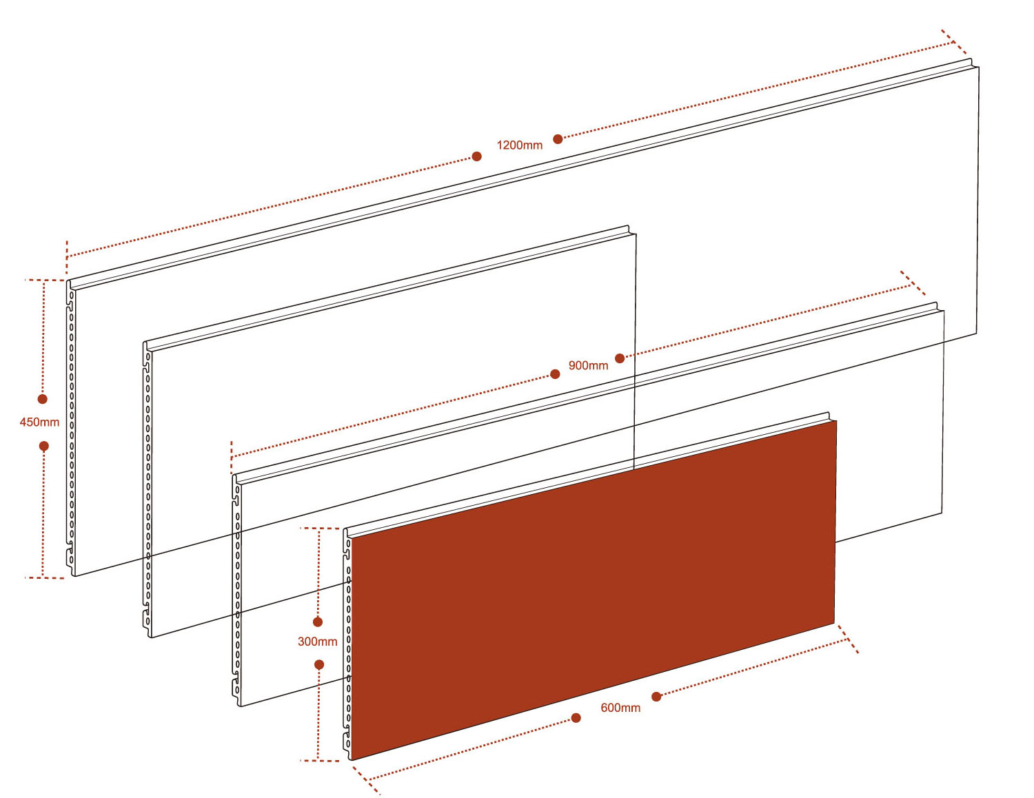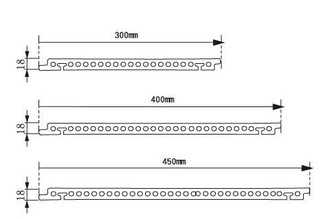
Terracotta panel size should emerge from the facade module, current manufacturing capability, project actions, engineered support system, tolerances, logistics, handling, openings, corners and replacement strategy. A historic dimension range is neither a current availability promise nor a universal span guide.

Start with the elevation module
Develop panel width, length, orientation and joint rhythm from the complete elevation rather than selecting the largest nominal piece first. Coordinate structural grids, floors, windows, doors, corners, parapets, soffits, bases and transitions to other materials. The module should resolve both typical fields and special zones.
Test the composition at several scales. A format that looks calm in a broad rendering may create narrow cuts around openings or awkward returns close up. Joint depth, backing color, profile geometry and surface finish can change how the same nominal size is perceived.
Create a rationalized panel schedule that records each type, orientation, profile and special condition without hiding unique pieces inside a typical mark. The schedule should connect to elevations and support drawings so architectural revisions do not leave orphaned panel codes in procurement.
Provide exact inputs for engineering
Identify current profile code and cross-section, actual mass data, orientation, finish, joints, fixing interfaces and facade zones. Project professionals determine relevant actions and combinations for the building, location, exposure, substrate and local design basis, then trace them through panel and support system.
This page provides no universal maximum panel size, load, span, support spacing, anchor arrangement or installation instruction. Engineering decisions need the exact panel, clips, rails, brackets, fasteners, anchors and supporting structure plus current calculations, tests or assessments that represent the proposed configuration.
Zone schedules should distinguish field, edge, corner, opening and other project cases where actions or details differ. Controlled reactions and assumptions need to pass between responsible designers. A dimension accepted in one facade zone does not automatically establish suitability elsewhere.
Verify current manufacturing feasibility
Ask the manufacturer to review requested dimensions with profile geometry, extrusion, firing, cutting, finish, orientation, quantity and programme. Current feasibility may vary among flat panels, deep profiles, special shapes and treatments. One dimension cannot be separated from the others.
Agree controlled tolerances and the production inspection approach for the exact item. Review length, width, thickness, straightness, bow, twist, diagonal and interface geometry as relevant. A fired sample or prototype supports only its identified profile, size and production route.
Use production-representative samples at meaningful dimensions rather than relying only on small color pieces. If a trial prompts a profile, size or process revision, update architectural studies, engineering evidence, packaging assumptions and the component schedule before the design is frozen.

Coordinate transport, handling and access
Factory handling
Review production movement, inspection and packaging with the exact fired format and finish.
Transport chain
Confirm crates, route constraints, lifting interfaces and delivery sequence through project logistics planning.
Site access
Assess storage, facade access, equipment and work zones under the contractor’s approved project plan.
Replacement access
Consider how a future panel can be identified, reached and replaced within completed junctions.
A manufacturable panel is not automatically practical to transport or handle on a particular site. Logistics findings may prompt a revised module, but changes must return to architectural, engineering and system-interface review rather than being treated as a procurement-only decision.
Packaging and delivery sequencing should preserve component identity and relate to the planned facade areas. Review route, storage and access constraints early enough to influence the module responsibly. Damage or unexpected handling issues need formal assessment, not relocation to a less visible elevation.
Resolve openings, corners and terminations
Prepare condition schedules for window heads, jambs and sills, external and internal corners, returns, doors, penetrations, parapets, soffits and bases. Identify full modules, controlled cut pieces where approved, special shapes and endpoints. Coordinate supports and control layers at each condition.
Use the current profile and tolerance chain to check cumulative alignment across those junctions. Field cutting or improvised support should not compensate for an unresolved size strategy. Any permitted fabrication or adjustment belongs in current approved manufacturer and project documents.
Mock up a representative junction where module choice materially affects appearance or system access. Review cut-edge visibility, joint continuity, support depth, water-management interfaces and replacement path together. A typical field sample cannot answer all of those special-condition questions.
Plan variation, lots and replacement
Larger visual fields may make color, finish or alignment variation read differently than smaller modules. Use representative fired samples and a facade mock-up to review the selected format, joints, supports and adjoining materials. Connect approvals to exact profile and production revisions.
Maintain lot identity and installed-location records. Retain correctly identified spares where the project requires them, while acknowledging that a future fired batch may not match the original exactly. Replacement planning should include interface access and current system review, not dimensions alone.
Freeze a buildable, evidenced size schedule
Before release, align elevations, panel schedules, support drawings, calculations, evidence, mock-up conclusions, tolerances, logistics and quality records. A changed length, width, thickness, profile or orientation may affect multiple packages and should enter formal change control.
Explore the terracotta panel range and rainscreen project gallery for design context, then confirm current manufacturing and engineered-system feasibility.