LOPO Terracotta baguette size, color and surface texture

A terracotta baguette specification schedule turns a visual idea into controlled fields for format, colour, texture, tolerance, location and system evidence.

Use it to connect every elevation mark to a current product drawing, approved range samples, an assembly bay and project responsibilities. A photograph or a generic family name cannot establish a model, size, colour code, manufacturability or safe span.

Archive boundary: the 2022 article contains one outdoor sample-display photograph and a separate close-view featured image. Neither includes a readable item number, dimension, colour/finish code, project identity or approved fixing detail. No SKU, size or capability has been imported from another product page.

Give this page one clear job

This is a scheduling and approval resource. Use the current product page to identify candidate families, the geometry guide to coordinate section/orientation/spacing, the series guide to separate element and assembly scope, and the louver-composition guide to control rhythm and colour at building scale. This page records the selected outcome so drawings, samples, production, delivery and installation refer to the same information.

Related resources and their separate roles
ResourcePrimary decisionWhat it does not replace
Terracotta BaguetteCurrent product-family discovery and enquiryProject schedule, shop drawings, engineering, approvals or assembly testing
Geometry CoordinationSection, direction, angle, spacing, openings, corners and support conceptControlled finish/batch schedule and production release
Baguette Series GuideElement identity and complete louver/screen system responsibilitiesProject-specific colour/texture range and elevation mapping
Louver CompositionBuilding-scale rhythm, density, colour proportions and viewpointsItem-level dimensions, tolerances, batches or acceptance records

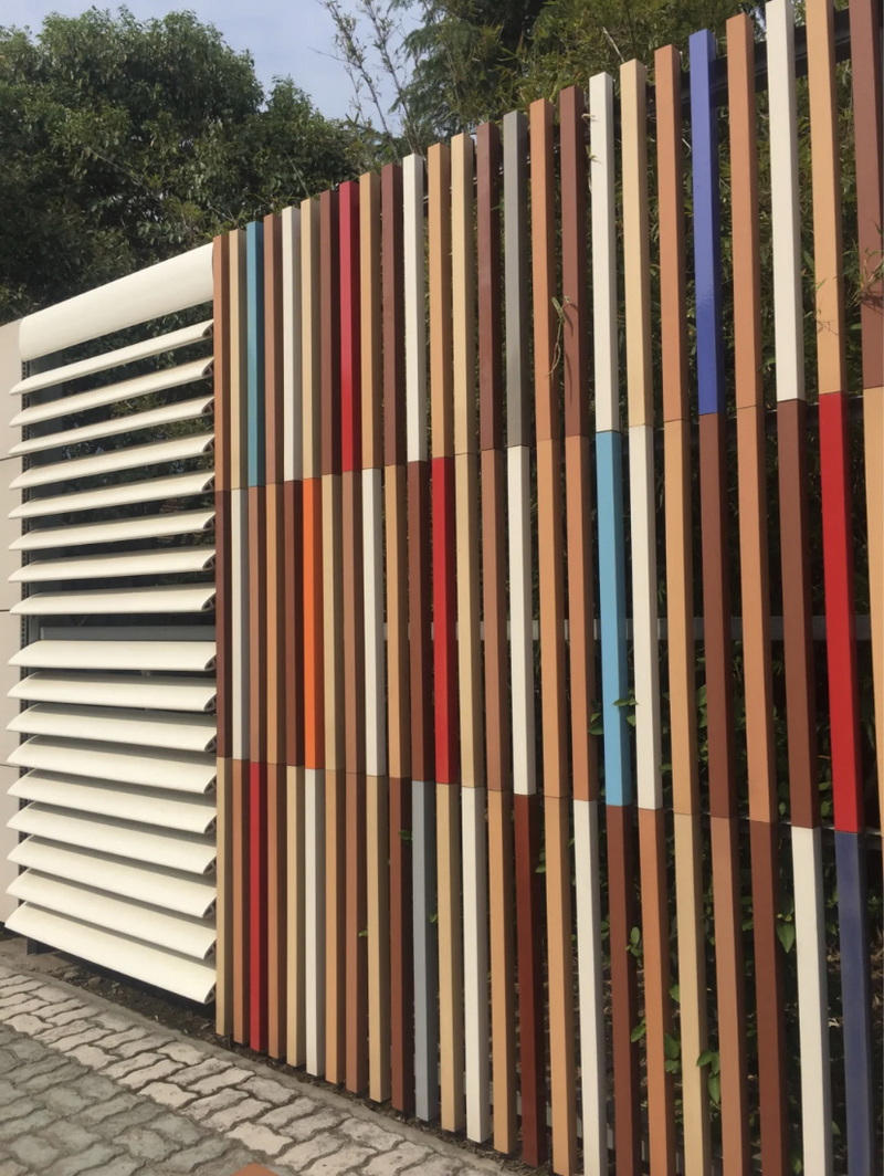
Outdoor display of vertical multicolour rectangular baguette-like samples beside horizontal pale louver-like pieces
The full 800 × 1064 archive photograph shows a visual sample display. It is not a current colour chart, dimensional schedule, project bay, support detail or performance test.

Build the format, colour and texture schedule

Assign a unique type mark to each intentionally different element family. Do not use one type for units that differ in section, length, orientation, finish, colour range, end treatment, support interface or acceptance criteria. Cross-reference the mark on elevations, plans, sections, details, quantities, sample records and shop drawings.

Minimum schedule fields
Field groupRecord for each type markControl document
IdentityType mark, elevation/zone, intended function, current manufacturer/item or approved custom-development reference, plant and drawing revisionProduct data, controlled section drawing and finish record
Section and endsDimensioned profile, cavities/walls and support zones as applicable; orientation; end condition; permitted factory/site cuts, holes, inserts or capsManufacturer’s current fabrication limits plus project engineering
Length and setting outRequired unit length, cut list, joint/termination logic, datum, repetition pitch, angle/rotation and relationship to openings, corners and structureCoordinated elevations, schedules and shop drawings
Body and colourBody/finish route, colour reference, permitted range, distribution/mixing rule, gloss where relevant and relationship to adjacent panels/materialsLabelled control and boundary samples, colour map and approved mock-up
Surface textureTexture name/reference, direction, face/edge/end treatment, intentionally exposed faces, permitted variation and cleaning restrictionsPhysical samples, finish process record and trial-cleaning result
Geometry/toleranceProject acceptance fields for section, length, straightness, bow, twist, squareness, end cut, hole/insert position and fit with supportsApplicable specification/method, approved product data and inspection plan
Mass and support interfaceDeclared unit mass, support points/zones, bearing/retention interface, movement allowance and orientation-dependent restrictionsCurrent product data, engineered assembly drawings and calculations
Quantity and traceabilityNet and spare quantities, waste/breakage assumptions, batch/lot and pallet map, installed location, replacements and retention periodProcurement schedule, delivery records and as-built asset register
Evidence statusRequired product/assembly tests, calculations, certificates/declarations, mock-ups, approvals, hold points and responsible partySubmittal register and responsibility matrix
Do not scale photographs. The display may make sections look rectangular or colours look matched, but perspective, lighting, camera processing and unknown supports prevent dimensional or colour identification.

Approve a range, not a single attractive sample

Fired-clay bodies and applied finishes may vary by process, batch, profile, orientation and light. Define which variation is intended, tolerated or rejected for the selected current item. A colour used on a panel family is not automatically available or visually equivalent on a baguette section; compare physical samples from the proposed section and process.

Control sample

Label the nominal approved reference with item/profile, finish process, colour reference, plant, batch/date and approval status. A loose unlabelled piece is not a durable control.

Boundary samples

Approve acceptable light/dark, hue, texture, gloss, speckling, pinholes, edges, ends and other relevant extremes. Record whether distribution is random, blended or mapped.

Installed range

Review representative quantities in the actual direction, spacing and background under sun, shade, overcast and project lighting, from priority exterior and interior viewpoints.

Colour and texture review questions

  • Is colour inherent to the body, engobe, glaze, coating or another declared finish route, and which faces/ends receive it?
  • How will cuts, drilled zones, caps, inserts, sealants, metals and damaged edges appear?
  • Does texture direction change with vertical, horizontal, angled or rotated installation?
  • How will shade, wetting, runoff, dust, biological growth, adjacent planting and artificial light affect appearance?
  • What cleaning method has been trialled on the exact finish and adjacent materials, and what tools/chemicals are prohibited?
  • How will batches be blended, mapped and recorded, and how will future replacements be assessed against weathered work?

Make geometry and tolerance measurable

A family name such as square, rectangular, oval, triangular or shuttle describes intent only. Release a product only against a current dimensioned section and length schedule. The project team, manufacturer and system designer must agree measurement methods, sampling, acceptance criteria and escalation for every tolerance that affects appearance, assembly fit or safety.

Geometry review from unit to facade
Single unitProfile dimensions, walls/cavities, length, mass, straightness, bow, twist, end cut, edge condition and support/insert zones.
Repeated fieldPitch, clear gap, angle/rotation, joint alignment, colour/texture distribution, cumulative drift, visible supports and shadow pattern.
InterfacesStarts/stops, corners, curves, parapets, bases, openings, doors, glazing, opaque walls, horizontal bands, penetrations and adjacent materials.
Movement and tolerancesBuilding/substrate movement, rail/bracket adjustment, element movement, installation sequence and how permitted variation is absorbed without forced fit or unintended contact.
Damage and replacementHandling points, protection, inspection access, damage criteria, safe removal/reinstatement, independent retention where required and compatible spare units.

Do not invent a universal allowable bow, twist, span, hole position, joint, support spacing or cut length. Match values to the selected geometry, current manufacturing capability, engineered assembly and applicable project requirements.

Use staged samples and mock-ups

Freeze the design intent

Approve elevation zones, type marks, directions, density, colour proportions, texture, background and priority viewpoints before requesting production samples.

Confirm current feasibility

Submit each proposed section/length/finish combination for written feasibility, minimum quantities, lead time, tooling, tolerances, ends and support-interface review.

Approve labelled ranges

Record nominal and boundary samples from the proposed item/profile and process. Link every sample to the schedule and submittal revision.

Inspect a single element

Check section, length, straightness, twist, edges/ends, finish and fit with real support components before assembling a field.

Build a representative bay

Include actual orientation, spacing, supports, joints, background, corners/openings/terminations and adjacent materials; review all priority viewpoints.

Validate required performance

Where applicable, test the complete representative assembly to the approved structural, enclosure, fire, solar/daylight or other project plan.

Approve first production/installation

Verify production batch, packaging, installed setting out, colour distribution, supports, damage and records before unrestricted manufacture or installation.

Close the traceability loop

Update batch/pallet and installed-location maps, nonconformances, replacements, spares, as-builts and maintenance information.

Verify the complete louver or screen assembly

A baguette is one element. Any louver, screen or shading field also includes supports, connections, substrate and building interfaces. The responsible project team must define system scope and verify the exact assembly; a colourful display does not prove sun control, ventilation, structural safety or facade performance.

Assembly evidence gates
Structure and retentionEngineer self-weight, wind, seismic actions where applicable, impact, eccentricity, spans, end/intermediate supports, rails/brackets/anchors/inserts, substrate, movement, tolerances, damage and falling-object mitigation.
Solar/daylight and viewsIf shading is intended, analyse actual orientation, section, angle, spacing, glass, occupied zones, climate and controls. Coordinate daylight, glare, views and whole-building energy separately.
Water and enclosureOpen baguettes do not form the primary air/water wall. Coordinate background wall/glazing, cavity, drainage, flashings, penetrations and interfaces without trapping water in elements or supports.
Fire and regulated edgesConfirm product and assembly fire evidence, cavity/fire-stopping interfaces and local rules. A decorative field is not automatically a guard, balustrade, fall barrier or climb-prevention system.
Thermal/acoustic/environmentalDo not attribute insulation, sound reduction, energy savings or environmental superiority to an isolated element. Use defined complete-system calculations/tests and current scoped declarations.
Durability and maintenanceMatch finish, element, metals/connections and cleaning/access strategy to the exposure. Define inspection, damage response, safe replacement, spares and responsibility.
Engineering boundary: no schedule entry approves a load, span, fixing, support spacing, drilled/cut condition or regulated safety function. Those require the current element geometry and project-specific design, evidence and authority acceptance.

Control procurement, delivery and handover

Before purchase, reconcile the approved schedule with quantities, elevations, shop drawings, calculations/tests, tooling and finish samples. Record what is included and excluded: elements, cuts, holes/inserts/caps, supports, fasteners, packaging, spares, mock-ups/tests, freight, installation, inspection and warranty. Confirm current lead time and commercial terms rather than relying on the 2022 archive.

Delivery and acceptance record

  • approved type mark, item/profile/finish, drawing and sample revisions;
  • batch/lot/pallet identity, quantities, packaging condition and document completeness;
  • project-defined sample selection and checks for dimensions, straightness/twist, edges/ends, colour/texture and support-interface fit;
  • segregation, notification, disposition, reinspection and closure of nonconforming units;
  • installed-location map, inspections/tests, damage/replacement records and as-built changes; and
  • labelled spares, safe access/removal method, cleaning/maintenance plan and responsible parties.

Prepare the schedule enquiry

Share elevations and type marks; intended function; candidate section/profile and length; orientation, angle, pitch and joint/termination logic; colour/texture intent and distribution; openings/corners/interfaces; substrate/support concept; design actions; enclosure/fire/safety requirements; applicable standards; mock-up/testing plan; quantities, spares, programme and commercial scope.

Turn the visual brief into controlled submittals

Send the schedule fields, drawings, range-sample brief, system responsibilities, evidence requirements, quantities and programme. Product feasibility and project engineering should be confirmed before dimensions, colours or textures are released.