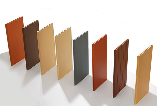
Hollow structure Grooved Terracotta Board from LOPO
Item No.:F253089
Material: 100% Natural Clay
Size: 250*1200*30mm
Usage: Wall Facade Decoration
CE, ISO9001:2008
Hollow structure Grooved Terracotta Board from LOPO introduction:
Introduction about Terracotta Board:
Terracotta Board is adopted raw material and firing production process, which is completely environmentally-friendly, even the waste material can be recycled. Terracotta Board has many feature and functions, for example, sound absorption, heat insulation, shockproof, windproof, self-cleaning, waterproof etc. With LOPO China’s special formula and advanced firing process, terracotta facade panel can meet various requirements from architects by natural texture and rich colors.
Terracotta Board has hard texture, neat and beautiful appearance, unique humanistic feelings and attraction from outside to inside. It is simple but grand, vigorous but restrained and couples hardness and softness, making architectures radiate human air and elegance and humbleness.
Terracotta Board demonstrates the beauty of architectural art with its unique glamour and manifest the height of architectural temperament with its generousness and smartness.
LOPO China Terracotta Panel Specification:
| Item No.: | F253089 |
| Material | 100% natural clay |
| Size(W*L*T): | 250*1200*30mm |
| Color: | Brown |
| Customized Design: | Available |
| Weight | 31kgs/sqm for 18mm thickness, 44kgs/sqm for 30mm thickness |
| Port: | Xiamen Port |
| Lead Time: | 20days after receiving deposit |
| Payment Term | L/C, TT, Western Union |
| Usage: | Exterior and Interior Wall Decoration |
| Application: | University, Apartment, Hospital, Railway Station, Mall etc. |
| Packing: | Wooden Crate |
| Certification: | CE, ISO9001:2008 |
LOPO China Regular Terracotta Products Specification:
| Regular Product | Color | White/Yellow/Grey/Red/Brown |
| Surface | Flat/Grooved/Sanded/Glazed/Linear/Wood/Corrugated | |
| Dry Hanging Terracotta Panel | Length | 250mm-1500mm |
| Width | 150mm-600mm | |
| Thickness | 18mm/30mm | |
| Small Size Terracotta Panel | Width | 100mm-200mm |
| Thickness | 10mm-15mm | |
| Light Weight Terracotta Panel | Length | 250mm-1500mm |
| Width | 150mm-600mm | |
| Thickness | 10mm-15mm | |
| Customized is welcome! Just send us your design or sample. | ||
Terracotta Facade Panel Features and Benefits:
1. Natural clay materials, eco-friendly
2. Hollow structure, light weight
3. No-static and no-radiation
4. Never fade, strong and durable
5. Convenient fixing installation, safe and reliable
6. Wind and earthquake resistance
7. Heat preservation and sound insulation
8. Self-cleaning, easy maintenance
Terracotta Board Technical Data Sheet:
| Terracotta Board Technical Data Sheet | ||||
| NO. | Contents | (300X600X18MM) Terracotta Board | China N. S. GB/T4100-2006 | EN14411 standard |
| 1 | Water Absorption | 5.4% | (II) 6-10% | (II) 6-10% |
| 2 | Net Weight | 31kg/m2 | no value | no value |
| 3 | Breaking Strength | 3475N | ≥ 900N | ≥ 750N |
| 4 | Frost Resistance | no crack under -60 centigrade | tested value of the report | tested value of the report |
| 5 | Modulus of Rupture | avg. 13.1Mpa, min 11.8Mpa | Avg. ≥ 9Mpa, single value≥ 8Mpa | Avg. ≥ 9Mpa, single value≥ 8Mpa |
| 6 | Earthquake Resistance | over 8 degree | no value | No |
| 7 | Test Under Simulated Wind Load | No breakage under 10Kpa | no value | No |
| 8 | Sound Insulation | Noise reduction by over 8dB | 7-10dB | No |
| 9 | Wind Pressure | 9kPa | tested value of the report | tested value of the report |
| 10 | Heat Conductivity | 0.32 w/m. k | no value | No |
| 11 | Fire Resistance | level A1 | no value | No |
| 12 | Resistance to Acid and Alkali | Level UA | tested value of the report | No |
| 13 | Radioactivity | Class-A decorative material | no value | No |
| 14 | Right Angle | 0.1%- -0.2% | within ±1% | No |
| 15 | Size Error | 300L: 0.1%- -0.4%600L: 0.2%- -0.5% | with in ±2% , max is within ±2mm, | No |
| 16 | Thickness Error | within ±4.5% | within ±10% | No |
| 17 | Diagonal Line | -0.5 ~ +0.2 Max 1.0mm | within ±2% | No |
LOPO China Production Ability:
1. Domestic longest roller kiln (260-meter) with 428 firing units;
2. 80,000 square meters open stockyard with the daily reserve of natural c lay raw materials amounts to 300,00 tons;
3. The new workshops and production lines under construction;
4. The semi-production indoor repository with storage capacity of 150,000 tons;
5. The automatic production line with the processing capacity of shaping, cutting and polishing;
6. A batch storage system which can reserve 12,000 tons of prepared clay materials;
7. Imported molding machines of vacuum extrusion from Italy.
Reference:
More about Terracotta Panel products, please refer: https://www.terracotta-panel.com/terracotta-cladding/