Modern terracotta brick design can translate courtyard scale, wall rhythm, framed openings and deep eaves without treating historic architecture as a catalogue of motifs.
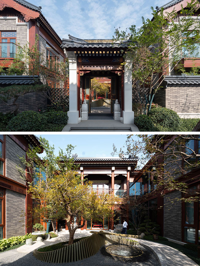
This archive-attributed Yizhou Ancient City reference shows one possible composition. The guide then separates cultural intent from the exact brick, masonry or facing system, water/fire strategy, mock-up and project approvals needed to build it.
Project record and evidence limits
| Verified identity | Yizhou Ancient City cultural-tourism project in Hedong District, Linyi, Shandong, China |
|---|---|
| Use | Cultural-tourism and commercial precinct; official sources describe planning, architecture/landscape and cultural-tourism operation without supplying project-design credits |
| Date boundary | The project was the subject of official site visits in November 2020 and March 2021. These dates confirm existence, not completion. The WordPress post date of December 2022 is also not a completion date. |
| Archive design account | The old LOPO text says the development draws on local Yizhou history, Ming/Qing building forms and garden precedents. This is retained only as the archive’s design narrative, not an independently verified historical or conservation assessment. |
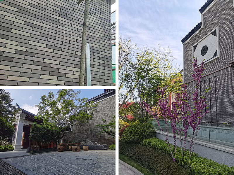
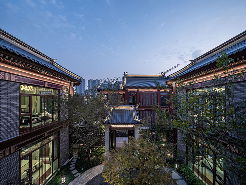
| Visible image set | Low-rise courtyard/gate ensemble with grey brick-like wall fields, tiled pitched roofs and eaves, dark/red-brown framing, glazing, stone bases and landscaped thresholds |
| Undisclosed fields | Architect/design team, completion year, photographer, manufacturer/supplier, LOPO role, product/SKU, unit geometry, area/quantity, masonry/facing/support route and project tests |
The project/location boundary follows the Linyi Culture and Tourism Bureau’s 2020 project record and its 2021 planning and architectural-landscape visit record. Neither source identifies the archived photographs or a LOPO material/system role.

Translate a specific place, not “Chinese architecture” as one style
China contains many regional, chronological and building traditions. A credible brief should identify the place, period, building type and source being interpreted; document which surviving records or local references inform the design; and involve suitable local history, heritage, planning or conservation expertise where cultural claims matter.
Translation can work through proportions, spatial sequence, material rhythm and environmental interfaces rather than copying generic symbols. State what is being carried forward, what is deliberately changed and why the contemporary programme requires that change.
Scale and sequence
Use wall height, courtyard width, gate depth, sheltered thresholds and changing views to create an inhabitable sequence. Test these against circulation, accessibility, egress, service and commercial needs.
Roof and wall hierarchy
Coordinate roof silhouette, eave depth, base/plinth and wall field as one composition. Do not treat the brick-like surface as evidence that the wall is traditional loadbearing masonry.
Material abstraction
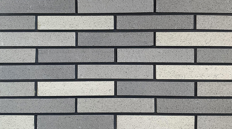
A fine grey module, controlled tone range and joint rhythm can reference masonry scale without imitating age. Record the exact contemporary material and assembly instead of relying on “ancient” appearance.
Turn visible references into measurable design fields
| Visible reference | Design question | Evidence to approve |
|---|---|---|
| Low-rise courtyard ensemble | Which public, private, service and accessible routes shape the courtyard proportions and entrances? | Plans/sections, route and level strategy, egress/accessibility review, landscape/water coordination |
| Gate and layered threshold | How do opening width/height, reveal depth, roof, doors and framed views mark transition without obstructing safe movement? | Dimensioned threshold details, door/hardware, drainage, lighting, security, signage and fire review |
| Grey modular wall field | What exact unit, tone range, bond and joint create the intended scale, and where do they change? | Current product/assembly data, labelled range samples, elevations, setting-out drawings and mock-up |
| Tiled roofs and projecting eaves | How are roof structure, loads, edge restraint, rainwater, snow/wind where applicable and wall junctions resolved? | Engineered roof/eave details, weathering/drainage, fire and maintenance access evidence |
| Dark/red-brown frames and glazing | How do contemporary windows/doors meet masonry-like walls without confusing support, movement or enclosure layers? | Heads/jambs/sills, flashings, sealants, anchors, thermal/fire/water continuity and replacement access |
| Stone base and planting | How are splash, soil/irrigation, drainage, rising moisture, salts and cleaning kept away from vulnerable interfaces? | Base/plinth, waterproofing, falls/drains, planter and material-compatibility details plus maintenance plan |

Set scale from place to unit
Coordinate three scales together. At precinct scale, map streets, courts, gates and rooflines. At building scale, align wall bays, openings, bases, eaves and structure. At unit scale, use the exact proposed unit plus joint to establish bond, coursing, cuts, corners and cumulative tolerance.
- establish datums from surveyed structure, finished floor levels, openings, roof/eave lines and priority views;
- record the exact unit face/back/section, dimensions/tolerances, mass, finish and intended orientation;
- draw bond and colour/tone distribution rather than describing the field as random or traditional;
- coordinate full units, permitted cuts, small pieces, corners/returns, bases/tops and movement locations;
- resolve windows, doors, gates, grilles, signage, services, lights and access panels without breaking required support or enclosure layers;
- separate masonry/facing support from decorative timber, metal, stone or roof elements; and
- approve representative elevations and critical interfaces at full scale before quantities and fabrication are released.
No unit size, joint width, bond, colour ratio, cut rule or tolerance can be taken from these archive images. The old phrase “three grades of grey mixed randomly” is not a measurable project specification and is not carried forward.

Choose and document the real wall route
A brick-like appearance can be produced by structurally different assemblies. Identify the route before detailing the pattern; do not use the word “brick” as a substitute for load path, enclosure or fire design.
| Route | Project coordination | Evidence gate |
|---|---|---|
| Structural or supported masonry | Foundation/support, wall thickness, openings, restraint/ties, movement, stability, interfaces, workmanship and local masonry rules | Structural design, unit/mortar data, details, calculations, tests/inspections and authority approval |
| Anchored veneer | Support at base/openings, backing, cavity, ties/anchors, drainage/ventilation where designed, movement, flashings and weeps | Complete veneer/backing design and project-relevant product/assembly evidence |
| Adhered brick slip/tile | Exact intended-use product, substrate/preparation, setting/grout, movement, moisture/temperature exposure, edges and safe repair | Matched product/system data, project substrate/exposure validation and installation QA |
| Mechanically retained facing | Unit geometry/mass, rails/brackets/anchors, structure/substrate, tolerances, movement, joints, drainage and replacement | Engineered system drawings/calculations, material compatibility and required assembly tests |
| Freestanding/open screen | Independent support, out-of-plane/impact actions, openings, guarding/falling-object risk, fire, egress and maintenance access | Project engineering and regulated-assembly approval; screen appearance does not prove safety |
Where different routes meet in one precinct, use separate type marks and details. A colour match between masonry, tile, facing and roof products does not make their dimensions, movement, weathering or support requirements interchangeable.
Resolve openings, corners, bases and eaves as one envelope
Coordinate heads, jambs and sills with the structural opening, support/retention, air/water layers, insulation, fire control, movement and window/door anchorage. Protect visible edges and decide whether returns use purpose-made pieces, whole units, approved cuts, trim or another detail. Do not hide a required movement or drainage joint simply to maintain a continuous historic-looking bond.
At the base, resolve support, splash, ground/paving levels, rising moisture, salts, drainage and access for inspection. At the top, coordinate the wall with roof framing, eave/soffit, gutters and downpipes or other rainwater strategy, flashings, ventilation where designed, fire interfaces and safe maintenance. A deep eave reduces some exposure only if the project geometry and weather confirm it; it does not eliminate water management.

Replace material stories with current evidence
The old article’s manufacturing and performance claims—20 processes, 36-hour firing at 1300°C, 100-year life, automatic fire/pest/temperature resistance, low carbon, energy efficiency, easy reuse/recycling and wellbeing—are not tied to an identified product, plant, system, method or project record. They are excluded from the replacement.
| Identity and geometry | Manufacturer/plant, current item or controlled custom reference, intended use, body/finish, front/back/section, dimensions/tolerances, mass, edges/corners and permitted cuts/penetrations. |
|---|---|
| Appearance | Labelled control/boundary samples, tone/texture range, joint/bond drawings, distribution plan, lighting/viewing conditions and representative mock-up. |
| Structure and attachment | Complete load path, support/setting components, substrate/structure, anchors/ties/rails or mortar/adhesive as applicable, movement, impact and replacement. |
| Envelope and durability | Project exposure, water/drainage, thermal/moisture, freeze-thaw/salts where applicable, corrosion/material compatibility, cleaning and maintenance evidence for the complete build-up. |
| Fire and regulation | Current product/assembly evidence matched to visible units, setting/support, backing, membranes, insulation, cavities, joints, penetrations and applicable local requirements. |
| Environmental claims | Current product- and plant-matched declaration with defined scope, declared unit, life-cycle stages, method and verification; no conclusion from clay origin, fired appearance or potential recyclability. |
Use a project-specific translation workflow
Write the cultural brief
Name the specific place, periods, sources, spatial/material principles and responsible cultural/heritage reviewers; avoid generic national-style claims.
Map scale and sequence
Coordinate precinct routes, courtyards, gates, building proportions, openings, eaves, landscape, accessibility, egress and operations.
Select the wall route
Separate structural masonry, veneer, adhered or mechanically retained facing and screen types; assign exact responsibilities and evidence.
Approve product and range
Use current labelled units, dimensioned sections and boundary samples; draw module, bond, tone distribution, joints, cuts and interfaces.
Build and test a mock-up
Include a representative opening/corner, base/top/eave, adjacent materials and real support/enclosure layers; run project-required tests.
Record construction
Approve first work, batch/location, inspections, tests and nonconformances; hand over as-builts, cleaning, spares and repair methods.
Use related product and design resources
Use current product pages to identify candidates and the linked composition guides to develop visual options. None replaces the project cultural brief, exact-product record, coordinated assembly, engineering, mock-up or approvals.
Prepare a culturally grounded brick enquiry
Share the place-specific design brief, plans/elevations, wall type, dimensions, structure/substrate, climate/exposure, openings/eaves, finish and range intent, adjacent materials, maintenance conditions and applicable requirements. LOPO can review candidate fired-clay units and samples; the project team remains responsible for cultural interpretation, the complete wall, engineering and approvals.